In this blog I will try to explain basics of networking concepts and how these concepts are used to create simple to complex networking topologies to transfer data between physical machines and with the use of network namespaces on Linux we will try to simulate various scenarios as we discuss the theory behind them.
Network Segments
A network segment refers to a distinct part of a computer network that is isolated from the remainder of the network by a specific device, such as a repeater, hub, bridge, switch, or router. Within each segment, one or more computers or other hosts may reside. Depending on how these devices are connected, the network forms L1, L2 or L3 segments, Here the segment are mainly named on the basis of the layer of OSI networking model in which a segment mainly communicates.
An L1 segment is formed by a physical connection between networked devices, where each node on a single segment have a common physical layer When multiple L1 segments are connected by a shared switch (or bridge), an L2 network segment is formed. A L2 segment can also be formed recursively, i.e. merging multiple L2 segments via an upper layer switch to form a tree like topology.
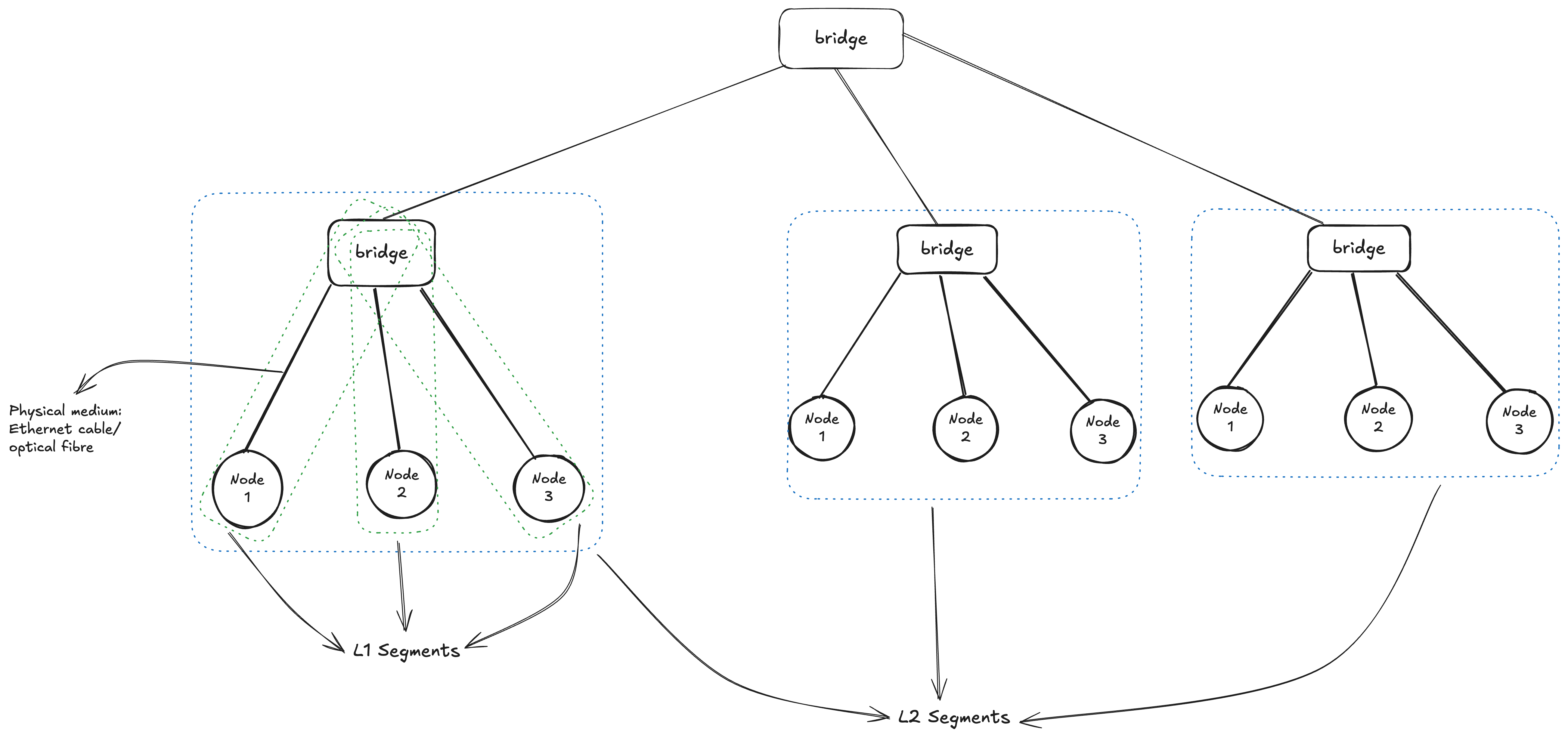
At its fundamental level, each L2 (Layer 2) segment operates as an independent broadcast domain. This means that every device connected within that specific segment has the capability to send a message that will be received by all other devices on the same segment. This form of “one-to-all” communication, known as broadcasting, takes place at Layer 2 of the OSI Model (the Data Link Layer), where devices primarily use MAC addresses and Ethernet frames to communicate. When several individual L2 segments are interconnected or “merged”: For example, by a network switch, They effectively combine to form a single, larger L2 segment. The significant implication of this merging is the creation of a much bigger broadcast domain. Within this expanded domain, a broadcast message initiated by any device will now reach every other device across the entire consolidated segment, allowing for broader Layer 2 communication across the network.
Note: VLAN can be used to split broadcast domains at the data link layer, Later on we will see how to use VLAN to partition a broadcast domain within a single L2 segment
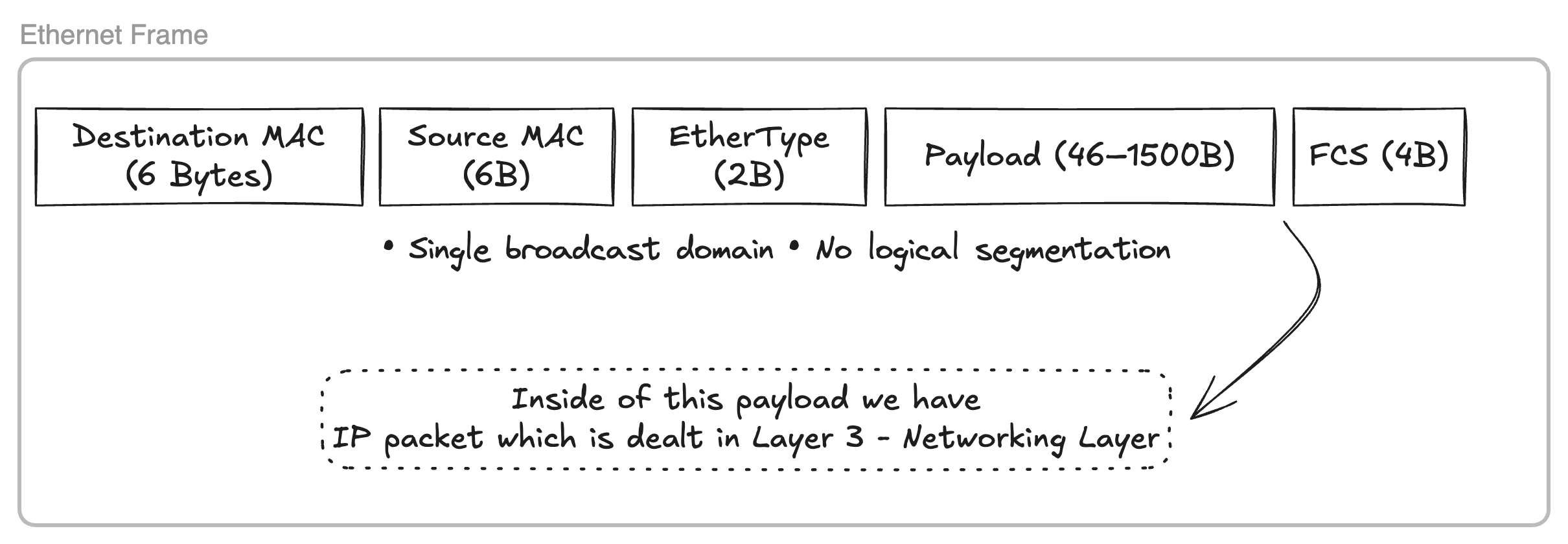
The accompanying diagram illustrates the structure of a Layer 2 Ethernet frame. Communication between devices within a Layer 2 segment occurs through the generation of binary payloads conforming to this structure. Our goal is to develop custom Go code for writing raw Ethernet frames to a designated network interface.
Trying Broadcast Domain
With Linux network namespaces we can simulate a network topology as shown in the diagram above and try to broadcast Ethernet frames with destination MAC address of (ff:ff:ff:ff:ff:ff) and try to send frame to a specific node with its MAC address and see how the whole communication works, But before we jump into lets understand what network namespaces are.
Network Namespaces
Linux network namespaces offer a method to simulate a dedicated network environment for a Linux container. This is precisely why containers created by Docker are equipped with their own distinct network interfaces, IP stacks, routing tables, and firewall rules. One can conceptualize network namespaces as operating on a similar principle to C++ namespaces: they establish a scoped environment with its own set of “devices” that do not conflict with the host machine’s hardware, thereby creating a virtual device (a container) within the host system. We will be taking a slight detour to first understand how we can create a working network topology like above with network namespace on Linux.
Let’s first create a network namespace ns1 with ip netns
1laborant@ubuntu-01:~$ sudo ip netns add ns1
2laborant@ubuntu-01:~$ ip netns list
3ns1
The ip link command is used to display all devices available on the host machine. This command can also be run within a newly created network namespace, such as ns1, by utilizing nsenter. A file is mounted for each new network namespace at /run/netns/<namespace_name>, and this mounted file can be used with nsenter to make the specified network namespace active for a current shell session. As shown below, the ns1 namespace contains only a loop back device.
 1# ON HOST MACHINE
 2laborant@ubuntu-01:~$ ip link list
 31: lo: <LOOPBACK,UP,LOWER_UP> mtu 65536 qdisc noqueue state UNKNOWN mode DEFAULT group default qlen 1000
 4    link/loopback 00:00:00:00:00:00 brd 00:00:00:00:00:00
 52: bond0: <BROADCAST,MULTICAST,MASTER> mtu 1500 qdisc noop state DOWN mode DEFAULT group default qlen 1000
 6    link/ether 3a:4c:de:8c:05:55 brd ff:ff:ff:ff:ff:ff
 73: dummy0: <BROADCAST,NOARP> mtu 1500 qdisc noop state DOWN mode DEFAULT group default qlen 1000
 8    link/ether 7a:7e:34:4b:fb:cd brd ff:ff:ff:ff:ff:ff
 94: eth0: <BROADCAST,MULTICAST,UP,LOWER_UP> mtu 1500 qdisc pfifo_fast state UP mode DEFAULT group default qlen 1000
10    link/ether ba:58:08:f7:5c:14 brd ff:ff:ff:ff:ff:ff
11
12# ON NS1 namespace
13laborant@ubuntu-01:~$ ls -la /run/netns/
14total 0
15drwxr-xr-x  2 root root  60 Jan 10 16:19 .
16drwxr-xr-x 16 root root 440 Jan 10 16:19 ..
17-r--r--r--  1 root root   0 Jan 10 16:19 ns1
18
19laborant@ubuntu-01:~$ sudo nsenter --net=/run/netns/ns1
20root@ubuntu-01:laborant# ip link list
211: lo: <LOOPBACK> mtu 65536 qdisc noop state DOWN mode DEFAULT group default qlen 1000
22    link/loopback 00:00:00:00:00:00 brd 00:00:00:00:00:00
The initial step is to establish a L1 segment by creating a virtual Ethernet pair device. One interface of this pair will be positioned within the ns1 network namespace, while the other will reside on the host machine. A description of the veth device, available in its manual pages:
 1The veth devices are virtual Ethernet devices.  They can act as
 2tunnels between network namespaces to create a bridge to a
 3physical network device in another namespace, but can also be used
 4as standalone network devices.
 5
 6veth devices are always created in interconnected pairs.  A pair
 7can be created using the command:
 8
 9    # ip link add <p1-name> type veth peer name <p2-name>
10
11In the above, p1-name and p2-name are the names assigned to the
12two connected end points.
13
14Packets transmitted on one device in the pair are immediately
15received on the other device.  When either device is down, the
16link state of the pair is down.
Let’s create veth1 ⇿ ceth1 pair
1laborant@ubuntu-01:~$ sudo ip link add veth1 type veth peer ceth1
2laborant@ubuntu-01:~$ sudo ip link list | grep "veth1"
36: veth1@ceth1: <BROADCAST,MULTICAST,M-DOWN> mtu 1500 qdisc noop state DOWN mode DEFAULT group default qlen 1000
4    link/ether d6:d3:07:0b:a1:ce brd ff:ff:ff:ff:ff:ff
Now we need to place one end of the pair inside the ns1 namespace and toggle the state of both the ends to UP from DOWN mode
 1laborant@ubuntu-01:~$ sudo ip link set ceth1 netns ns1
 2laborant@ubuntu-01:~$ ip link ls | grep veth1
 36: veth1@if5: <BROADCAST,MULTICAST> mtu 1500 qdisc noop state DOWN mode DEFAULT group default qlen 1000
 4    link/ether d6:d3:07:0b:a1:ce brd ff:ff:ff:ff:ff:ff link-netns ns1
 5# Here veth1 is in DOWN mode
 6
 7laborant@ubuntu-01:~$ sudo ip link set veth1 up
 8laborant@ubuntu-01:~$ ip link ls | grep veth1
 96: veth1@if5: <NO-CARRIER,BROADCAST,MULTICAST,UP> mtu 1500 qdisc noqueue state LOWERLAYERDOWN mode DEFAULT group default qlen 1000
10    link/ether d6:d3:07:0b:a1:ce brd ff:ff:ff:ff:ff:ff link-netns ns1
11# Now it's in LOWERLAYERDOWN since the other end is still DOWN
12
13
14laborant@ubuntu-01:~$ sudo ip netns exec ns1 ip link set ceth1 up
15laborant@ubuntu-01:~$ sudo ip netns exec ns1 ip link ls
161: lo: <LOOPBACK> mtu 65536 qdisc noop state DOWN mode DEFAULT group default qlen 1000
17    link/loopback 00:00:00:00:00:00 brd 00:00:00:00:00:00
185: ceth1@if6: <BROADCAST,MULTICAST,UP,LOWER_UP> mtu 1500 qdisc noqueue state UP mode DEFAULT group default qlen 1000
19    link/ether d2:e0:87:f7:79:84 brd ff:ff:ff:ff:ff:ff link-netnsid 0
20
21laborant@ubuntu-01:~$ ip link ls | grep veth1
226: veth1@if5: <BROADCAST,MULTICAST,UP,LOWER_UP> mtu 1500 qdisc noqueue state UP mode DEFAULT group default qlen 1000
23
24# Now both ends are in UP mode
I have used
ip netns execto run the commands insidens1namespace, which is an alternative tonsenter.
With the above setup now we have a L1 segment with two devices veth1 and ceth1
Now to have a L2 segment we need to repeat the above steps to create multiple such veth pairs and then connect the host end of the pairs to a device of type bridge.
I have created two more namespaces ns2 and ns3 with veth2 ↔ ceth2 and veth3 ↔ ceth3 virtual ETH pairs respectively
 1laborant@ubuntu-01:~$ sudo ip netns add ns2
 2laborant@ubuntu-01:~$ sudo ip netns add ns3
 3laborant@ubuntu-01:~$ sudo ip link add veth2 type veth peer ceth2
 4laborant@ubuntu-01:~$ sudo ip link add veth3 type veth peer ceth3
 5laborant@ubuntu-01:~$ sudo ip link set ceth2 netns ns2
 6laborant@ubuntu-01:~$ sudo ip link set ceth3 netns ns3
 7laborant@ubuntu-01:~$ sudo ip link set veth2 up
 8laborant@ubuntu-01:~$ sudo ip link set veth3 up
 9laborant@ubuntu-01:~$ sudo ip netns exec ns2 ip link set ceth2 up
10laborant@ubuntu-01:~$ sudo ip netns exec ns3 ip link set ceth3 up
11laborant@ubuntu-01:~$ ip link list
121: lo: <LOOPBACK,UP,LOWER_UP> mtu 65536 qdisc noqueue state UNKNOWN mode DEFAULT group default qlen 1000
13    link/loopback 00:00:00:00:00:00 brd 00:00:00:00:00:00
142: bond0: <BROADCAST,MULTICAST,MASTER> mtu 1500 qdisc noop state DOWN mode DEFAULT group default qlen 1000
15    link/ether 3a:4c:de:8c:05:55 brd ff:ff:ff:ff:ff:ff
163: dummy0: <BROADCAST,NOARP> mtu 1500 qdisc noop state DOWN mode DEFAULT group default qlen 1000
17    link/ether 7a:7e:34:4b:fb:cd brd ff:ff:ff:ff:ff:ff
184: eth0: <BROADCAST,MULTICAST,UP,LOWER_UP> mtu 1500 qdisc pfifo_fast state UP mode DEFAULT group default qlen 1000
19    link/ether ba:58:08:f7:5c:14 brd ff:ff:ff:ff:ff:ff
206: veth1@if5: <BROADCAST,MULTICAST,UP,LOWER_UP> mtu 1500 qdisc noqueue state UP mode DEFAULT group default qlen 1000
21    link/ether d6:d3:07:0b:a1:ce brd ff:ff:ff:ff:ff:ff link-netns ns1
228: veth2@if7: <BROADCAST,MULTICAST,UP,LOWER_UP> mtu 1500 qdisc noqueue state UP mode DEFAULT group default qlen 1000
23    link/ether 4a:f7:79:6e:5c:e6 brd ff:ff:ff:ff:ff:ff link-netns ns2
2410: veth3@if9: <BROADCAST,MULTICAST,UP,LOWER_UP> mtu 1500 qdisc noqueue state UP mode DEFAULT group default qlen 1000
25    link/ether 2a:b9:c0:6d:ed:05 brd ff:ff:ff:ff:ff:ff link-netns ns3
26laborant@ubuntu-01:~$ sudo ip netns exec ns2 ip link list
271: lo: <LOOPBACK> mtu 65536 qdisc noop state DOWN mode DEFAULT group default qlen 1000
28    link/loopback 00:00:00:00:00:00 brd 00:00:00:00:00:00
297: ceth2@if8: <BROADCAST,MULTICAST,UP,LOWER_UP> mtu 1500 qdisc noqueue state UP mode DEFAULT group default qlen 1000
30    link/ether ba:b6:2f:9a:96:71 brd ff:ff:ff:ff:ff:ff link-netnsid 0
31laborant@ubuntu-01:~$ sudo ip netns exec ns3 ip link list
321: lo: <LOOPBACK> mtu 65536 qdisc noop state DOWN mode DEFAULT group default qlen 1000
33    link/loopback 00:00:00:00:00:00 brd 00:00:00:00:00:00
349: ceth3@if10: <BROADCAST,MULTICAST,UP,LOWER_UP> mtu 1500 qdisc noqueue state UP mode DEFAULT group default qlen 1000
35    link/ether c6:ab:66:25:73:f9 brd ff:ff:ff:ff:ff:ff link-netnsid 0
Now we have all the veth pair in place, Let’s create a bridge device on host machine and connect all host end of newly created veth pairs to the bridge
 1laborant@ubuntu-01:~$ sudo ip link add br0 type bridge
 2laborant@ubuntu-01:~$ sudo ip link set veth1 master br0
 3laborant@ubuntu-01:~$ sudo ip link set veth2 master br0
 4laborant@ubuntu-01:~$ sudo ip link set veth3 master br0
 5laborant@ubuntu-01:~$ sudo ip link set br0 up
 6laborant@ubuntu-01:~$ ip link list
 71: lo: <LOOPBACK,UP,LOWER_UP> mtu 65536 qdisc noqueue state UNKNOWN mode DEFAULT group default qlen 1000
 8    link/loopback 00:00:00:00:00:00 brd 00:00:00:00:00:00
 92: bond0: <BROADCAST,MULTICAST,MASTER> mtu 1500 qdisc noop state DOWN mode DEFAULT group default qlen 1000
10    link/ether 3a:4c:de:8c:05:55 brd ff:ff:ff:ff:ff:ff
113: dummy0: <BROADCAST,NOARP> mtu 1500 qdisc noop state DOWN mode DEFAULT group default qlen 1000
12    link/ether 7a:7e:34:4b:fb:cd brd ff:ff:ff:ff:ff:ff
134: eth0: <BROADCAST,MULTICAST,UP,LOWER_UP> mtu 1500 qdisc pfifo_fast state UP mode DEFAULT group default qlen 1000
14    link/ether ba:58:08:f7:5c:14 brd ff:ff:ff:ff:ff:ff
156: veth1@if5: <BROADCAST,MULTICAST,UP,LOWER_UP> mtu 1500 qdisc noqueue master br0 state UP mode DEFAULT group default qlen 1000
16    link/ether d6:d3:07:0b:a1:ce brd ff:ff:ff:ff:ff:ff link-netns ns1
178: veth2@if7: <BROADCAST,MULTICAST,UP,LOWER_UP> mtu 1500 qdisc noqueue master br0 state UP mode DEFAULT group default qlen 1000
18    link/ether 4a:f7:79:6e:5c:e6 brd ff:ff:ff:ff:ff:ff link-netns ns2
1910: veth3@if9: <BROADCAST,MULTICAST,UP,LOWER_UP> mtu 1500 qdisc noqueue master br0 state UP mode DEFAULT group default qlen 1000
20    link/ether 2a:b9:c0:6d:ed:05 brd ff:ff:ff:ff:ff:ff link-netns ns3
2111: br0: <BROADCAST,MULTICAST,UP,LOWER_UP> mtu 1500 qdisc noqueue state UP mode DEFAULT group default qlen 1000
22    link/ether c6:e2:a8:ee:aa:be brd ff:ff:ff:ff:ff:ff
Bridge br0 has been designated as the master for veth1, veth2, and veth3. The ip link list output verifies this, indicating br0 as the master for each interface, alongside their corresponding pair endpoints (ceth) located within their respective network namespaces. This configuration effectively establishes a Layer 2 segment, interconnecting three devices through the bridge. The subsequent step involves testing both the broadcast domain and individual device connectivity through the transmission of Ethernet frames.
Testing the setup
This Go utility constructs raw Ethernet frames by sequentially concatenating the necessary components. It begins by appending the 6-byte destination MAC address (obtained from user input) to the frame. Next, it adds the 6-byte source MAC address (read from the specified network interface). Following this, a 2-byte EtherType (0x88B5 in this case) is appended to indicate the protocol carried in the payload. Finally, the actual payload data (“L2-test-from-go”) is added. This ordered byte sequence forms the complete Ethernet frame, which is then sent directly over the network interface using a raw socket (AF_PACKET).
We have started tcpdump on the host machine to monitor traffic on the br0 bridge interface. Correspondingly, tcpdump was also started on the ceth1, ceth2, and ceth3 interfaces within the ns1, ns2, and ns3 namespaces.
Host machine:
 1# Building the go snippet into executable binary
 2laborant@ubuntu-01:~$ go build -o l2_ping ./l2_ping.go
 3
 4# Listen for the traffic on network interfaces ceth1, ceth2 and ceth3 in ns1, ns2 and ns3 network namespaces respectively
 5laborant@ubuntu-01:~$ ip link list | grep br0
 66: veth1@if5: <BROADCAST,MULTICAST,UP,LOWER_UP> mtu 1500 qdisc noqueue master br0 state UP mode DEFAULT group default qlen 1000
 78: veth2@if7: <BROADCAST,MULTICAST,UP,LOWER_UP> mtu 1500 qdisc noqueue master br0 state UP mode DEFAULT group default qlen 1000
 810: veth3@if9: <BROADCAST,MULTICAST,UP,LOWER_UP> mtu 1500 qdisc noqueue master br0 state UP mode DEFAULT group default qlen 1000
 911: br0: <BROADCAST,MULTICAST,UP,LOWER_UP> mtu 1500 qdisc noqueue state UP mode DEFAULT group default qlen 1000
10laborant@ubuntu-01:~$ sudo tcpdump -i br0 -e -n
11tcpdump: verbose output suppressed, use -v[v]... for full protocol decode
12listening on br0, link-type EN10MB (Ethernet), snapshot length 262144 bytes
13
1408:51:05.394642 26:d7:11:b3:c8:e7 > 33:33:00:00:00:02, ethertype IPv6 (0x86dd), length 70: fe80::24d7:11ff:feb3:c8e7 > ff02::2: ICMP6, router solicitation, length 16
1508:51:06.521846 be:46:f3:5a:2b:27 > 02:77:f4:ad:6d:55, ethertype Unknown (0x88b5), length 29:
16        0x0000:  4c32 2d74 6573 742d 6672 6f6d 2d67 6f    L2-test-from-go
ns1 namespace:
1# Sending frame from ceth1 (ns1) to ceth2 (ns2)
2# Here `02:77:f4:ad:6d:55` is the MAC address of ceth2 interface in ns2 namespace as can be seen from the output of `ip link list` below
3root@ubuntu-01:laborant# ./networking/l2_ping ceth1 02:77:f4:ad:6d:55
4Sent Ethernet frame via ceth1 → 02:77:f4:ad:6d:55
ns2 namespace:
 1laborant@ubuntu-01:~$ sudo nsenter --net=/run/netns/ns2 bash
 2root@ubuntu-01:laborant# ip link list
 31: lo: <LOOPBACK> mtu 65536 qdisc noop state DOWN mode DEFAULT group default qlen 1000
 4    link/loopback 00:00:00:00:00:00 brd 00:00:00:00:00:00
 57: ceth2@if8: <BROADCAST,MULTICAST,UP,LOWER_UP> mtu 1500 qdisc noqueue state UP mode DEFAULT group default qlen 1000
 6    link/ether 02:77:f4:ad:6d:55 brd ff:ff:ff:ff:ff:ff link-netnsid 0
 7root@ubuntu-01:laborant# tcpdump -i ceth2 -e -n
 8tcpdump: verbose output suppressed, use -v[v]... for full protocol decode
 9listening on ceth2, link-type EN10MB (Ethernet), snapshot length 262144 bytes
10
1108:51:05.395138 26:d7:11:b3:c8:e7 > 33:33:00:00:00:02, ethertype IPv6 (0x86dd), length 70: fe80::24d7:11ff:feb3:c8e7 > ff02::2: ICMP6, router solicitation, length 16
1208:51:06.521868 be:46:f3:5a:2b:27 > 02:77:f4:ad:6d:55, ethertype Unknown (0x88b5), length 29:
13        0x0000:  4c32 2d74 6573 742d 6672 6f6d 2d67 6f    L2-test-from-go
ns3 namespace:
 1laborant@ubuntu-01:~$ sudo nsenter --net=/run/netns/ns3 bash
 2root@ubuntu-01:laborant# ip link list
 31: lo: <LOOPBACK> mtu 65536 qdisc noop state DOWN mode DEFAULT group default qlen 1000
 4    link/loopback 00:00:00:00:00:00 brd 00:00:00:00:00:00
 59: ceth3@if10: <BROADCAST,MULTICAST,UP,LOWER_UP> mtu 1500 qdisc noqueue state UP mode DEFAULT group default qlen 1000
 6    link/ether ce:3c:f4:76:12:a3 brd ff:ff:ff:ff:ff:ff link-netnsid 0
 7root@ubuntu-01:laborant# tcpdump -i ceth3 -e -n
 8tcpdump: verbose output suppressed, use -v[v]... for full protocol decode
 9listening on ceth3, link-type EN10MB (Ethernet), snapshot length 262144 bytes
10
1108:51:05.394921 26:d7:11:b3:c8:e7 > 33:33:00:00:00:02, ethertype IPv6 (0x86dd), length 70: fe80::24d7:11ff:feb3:c8e7 > ff02::2: ICMP6, router solicitation, length 16
1208:51:06.521858 be:46:f3:5a:2b:27 > 02:77:f4:ad:6d:55, ethertype Unknown (0x88b5), length 29:
13        0x0000:  4c32 2d74 6573 742d 6672 6f6d 2d67 6f    L2-test-from-go
Upon an initial transmission of a frame from ceth1 to ceth2, it first arrives at the bridge through veth1, which is the corresponding host end of the ceth1 interface. Because the bridge has no prior record of the Ethernet frame’s destination MAC address, it consequently floods this frame to all connected ports. This action clarifies why the Ethernet frame is observable in ceth3’s tcpdump. Nevertheless, following this initial transfer, the bridge learns and stores the source MAC address (corresponding to the ceth1 ↔ veth1 connection) and its associated port within its Forwarding Database (FDB). Consequently, when a frame is subsequently sent in the opposite direction, from ceth2 to ceth1, it will not be flooded to ceth2. This is because of the bridge now possessing knowledge of the precise port for the destination MAC address linked to the veth1 ↔ ceth1 pair.
ns1 namespace:
1# For reverse transmission from ceth2 -> ceth1, listening for traffic on ceth1 interface
2root@ubuntu-01:laborant# tcpdump -i ceth1 -e -n
3tcpdump: verbose output suppressed, use -v[v]... for full protocol decode
4listening on ceth1, link-type EN10MB (Ethernet), snapshot length 262144 bytes
509:24:00.347717 02:77:f4:ad:6d:55 > be:46:f3:5a:2b:27, ethertype Unknown (0x88b5), length 29:
6        0x0000:  4c32 2d74 6573 742d 6672 6f6d 2d67 6f    L2-test-from-go
ns2 namespace:
1# Sending frame from ceth2
2root@ubuntu-01:laborant# ./networking/l2_ping ceth2 be:46:f3:5a:2b:27
3Sent Ethernet frame via ceth2 → be:46:f3:5a:2b:27
ns3 namespace:
1laborant@ubuntu-01:~$ sudo nsenter --net=/run/netns/ns3 bash
2root@ubuntu-01:laborant# tcpdump -i ceth3 -e -n
3tcpdump: verbose output suppressed, use -v[v]... for full protocol decode
4listening on ceth3, link-type EN10MB (Ethernet), snapshot length 262144 bytes
5
6# No traffic visible on ceth3
The preceding tests have illustrated the functionality of L2 segments and broadcast domains. We have not yet addressed L3 segments or IP packets, as the current setup’s interfaces lack IP assignments, with communication happening at the L2 layer via MAC addresses. Moving forward, we will investigate how Layer 2 and Layer 3 cooperate to facilitate packet transmission using IP addresses.
L3 Segment
To enable communication using IP addresses, it’s necessary to first assign an IP address to every machine (or, in this context, to each ceth network interface of a network namespace). The ip addr add command facilitates this process.
1laborant@ubuntu-01:~$ sudo nsenter --net=/run/netns/ns1 bash
2root@ubuntu-01:laborant# ip addr add dev ceth1 192.168.0.1/24
3
4root@ubuntu-01:laborant# ip addr list | grep ceth1
55: ceth1@if6: <BROADCAST,MULTICAST,UP,LOWER_UP> mtu 1500 qdisc noqueue state UP group default qlen 1000
6    inet 192.168.0.1/24 scope global ceth1
Upon assigning an IP address and its corresponding subnet mask to an interface, the kernel automatically adds a route derived from the subnet mask’s information.
1root@ubuntu-01:laborant# ip route list
2192.168.0.0/24 dev ceth1 proto kernel scope link src 192.168.0.1
Consequently, all traffic destined for the 192.168.0.0/24 subnet will be directed through the ceth1 interface. Initially, all nodes (namespaces) will be assigned IP addresses, ensuring they are all part of the same subnet and reside within a single broadcast domain.
1root@ubuntu-01:laborant# ip addr list | grep ceth3
29: ceth3@if10: <BROADCAST,MULTICAST,UP,LOWER_UP> mtu 1500 qdisc noqueue state UP group default qlen 1000
3    inet 192.168.0.3/24 scope global ceth3
4
5root@ubuntu-01:laborant# ip addr list | grep ceth2
67: ceth2@if8: <BROADCAST,MULTICAST,UP,LOWER_UP> mtu 1500 qdisc noqueue state UP group default qlen 1000
7    inet 192.168.0.2/24 scope global ceth2
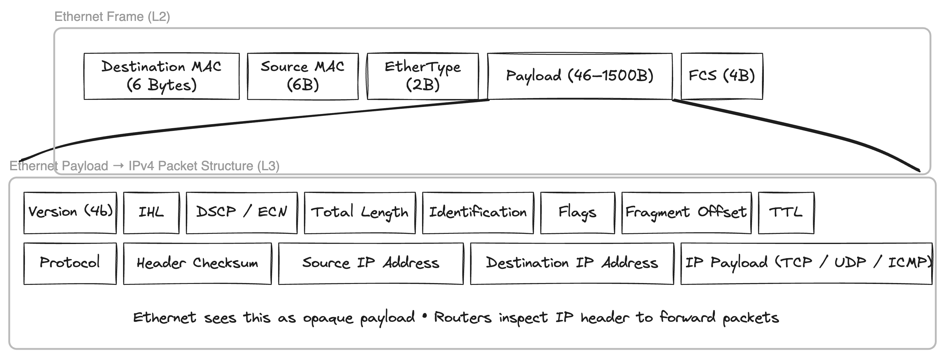
An IP packet also has source and destination IP addresses in its header and the whole IP packet is actually the payload of the Ethernet frame that we have seen above. Any L2 device will only deal with Ethernet frame headers and will treat anything inside the payload as it is, we have already seen this by sending raw bytes of string L2-test-from-go as the payload of the Ethernet frame while building the frame with l2_send go utility binary.
 If we send a
 ping (ICMP packet) from ceth1 to 192.168.0.3 i.e. node 3 with ceth3 interface then the sender needs to figure out the destination MAC address as ping will only populate the source and destination IP address. ARP (Address resolution protocol) comes into play to resolve the MAC address for a given IP address, Lets see it in action by capturing the packets coming to bridge br0 and all interfaces ceth0, ceth1 and ceth3 when we send the ping message.
1root@ubuntu-01:laborant# ping -c 1 192.168.0.3
2PING 192.168.0.3 (192.168.0.3) 56(84) bytes of data.
364 bytes from 192.168.0.3: icmp_seq=1 ttl=64 time=0.624 ms
4
5--- 192.168.0.3 ping statistics ---
61 packets transmitted, 1 received, 0% packet loss, time 0ms
7rtt min/avg/max/mdev = 0.624/0.624/0.624/0.000 ms
Step 1: Ping triggers routing decision in ns1
In ns1, the routing table is:
1root@ubuntu-01:laborant# ip route
2192.168.0.0/24 dev ceth1 proto kernel scope link src 192.168.0.1
So when I run:
1root@ubuntu-01:laborant# ping -c 1 192.168.0.3
the kernel in ns1 decides:
- The destination IP is in the same subnet
- The packet must go out via
ceth1 - No router or gateway is involved
At this point:
- An ICMP Echo Request is created at L3 (IP layer)
- No Ethernet frame can be built yet, because the destination MAC for
192.168.0.3is unknown
This missing MAC address is what triggers ARP.
Step 2: First ARP – broadcast from ceth1
Because ns1 does not know the MAC for 192.168.0.3, it sends an ARP request.
On br0, tcpdump -i br0 -e -n -vv shows:
1be:46:f3:5a:2b:27 > ff:ff:ff:ff:ff:ff, ethertype ARP (0x0806),
2Request who-has 192.168.0.3 tell 192.168.0.1
Important details here:
- Source MAC:
be:46:f3:5a:2b:27(MAC ofceth1) - Destination MAC:
ff:ff:ff:ff:ff:ff(broadcast) - This ARP is generated by the IP stack in ns1, not by the bridge
Bridge behaviour at this stage
When this frame enters br0 via veth1:
- The bridge learns the source MAC:
be:46:f3:5a:2b:27 → veth1
- Because the destination MAC is broadcast, the bridge floods the frame to all other ports (broadcast domain)
This explains why:
ceth3sees the ARP request (expected, it owns 192.168.0.3)ceth2also sees the ARP request, even though it is not involved:
be:46:f3:5a:2b:27 > ff:ff:ff:ff:ff:ff, ARP who-has 192.168.0.3 tell 192.168.0.1
Step 3: ARP reply from ceth3 – unicast
Since ns3 owns 192.168.0.3, it replies with an ARP reply.
On br0:
1ce:3c:f4:76:12:a3 > be:46:f3:5a:2b:27, ethertype ARP (0x0806),
2Reply 192.168.0.3 is-at ce:3c:f4:76:12:a3
Key points:
- Source MAC:
ce:3c:f4:76:12:a3(MAC ofceth3) - Destination MAC:
be:46:f3:5a:2b:27(MAC ofceth1) - This is a unicast ARP reply - targeted for
ceth1
Bridge behaviour here
When this frame enters br0 via veth3:
- The bridge learns another MAC:
ce:3c:f4:76:12:a3 → veth3
- The destination MAC (
be:46:f3:5a:2b:27) is already known - The frame is forwarded only to veth1 Because of this:
ceth1sees the ARP replyceth2does not see it This is the first point where flooding stops and unicast forwarding begins.
Step 4: ICMP echo request and reply (pure unicast)
After receiving the ARP reply, ns1 now has an ARP cache entry:
1root@ubuntu-01:laborant# ip neighbour show
2192.168.0.3 dev ceth1 lladdr ce:3c:f4:76:12:a3 STALE
Now ns1 can finally construct the Ethernet frame for the ICMP packet.
On br0, the ICMP Echo Request appears as:
1be:46:f3:5a:2b:27 > ce:3c:f4:76:12:a3, ethertype IPv4 (0x0800),
2192.168.0.1 > 192.168.0.3: ICMP echo request
The reply from ns3:
1ce:3c:f4:76:12:a3 > be:46:f3:5a:2b:27, ethertype IPv4 (0x0800),
2192.168.0.3 > 192.168.0.1: ICMP echo **reply**
Bridge behaviour during ICMP
At this point:
- The bridge FDB (Forwarding database) already contains both MACs
- Every ICMP frame is forwarded only between veth1 and veth3
- No flooding occurs
ceth2sees no ICMP traffic at all This confirms that the bridge is now operating in fully learned unicast mode.
Step 5: Why a second ARP is sent by ceth3
A few seconds later, this appears on br0:
1ce:3c:f4:76:12:a3 > be:46:f3:5a:2b:27, ethertype ARP (0x0806),
2Request who-has 192.168.0.1 tell 192.168.0.3
This often causes confusion. Important clarifications:
- This is not reverse ARP (RARP)
- This is a normal ARP request initiated by
ns3
Why ns3 needs this ARP
In ns3, the ARP entry for 192.168.0.1 is in STALE state:
Linux neighbour entries:
- Age out over time
- ICMP traffic alone does not guarantee permanent freshness
- When the entry is stale and traffic is needed, Linux probes using ARP
So ns3 asks again:
“Who has 192.168.0.1?”
Step 6: Why this second ARP does NOT reach ceth2
This is the most subtle and important point. Look closely at the Ethernet header:
1ce:3c:f4:76:12:a3 > be:46:f3:5a:2b:27, ethertype ARP
The destination MAC is not broadcast. This means:
ns3already knows the MAC address of192.168.0.1- Therefore it sends a unicast ARP request
Bridge behaviour for this ARP
When the frame enters br0 via veth3:
- The bridge already has this FDB entry:
1be:46:f3:5a:2b:27 → veth1
- The destination MAC is known
- The bridge forwards the frame only to veth1
- No flooding occurs
As a result:
ceth1sees the ARP request and repliesceth2sees nothing, even though this is an ARP request
Final summary (key points)
- A
pingfirst triggers ARP because the destination MAC is unknown. - The first ARP is broadcast and flooded across the bridge.
- The ARP reply allows the bridge to learn MAC locations.
- ICMP traffic then flows purely as unicast.
- ARP cache entries can become
STALE, triggering additional ARP probes. - These later ARPs can be unicast, not broadcast.
- Because the bridge already knows the destination MAC, it forwards such ARPs only to the correct port.
- This is why
ceth2saw the first ARP but did not see the second one.
Overall, this trace cleanly demonstrates:
- ARP is always generated by hosts (namespaces), not by the bridge
- The Linux bridge is strictly Layer 2, using only its FDB to forward frames
- Flooding happens only until MAC learning converges
ARP traffic can be seen in your home router as well by running
tcpdumpon the Wi-Fii interface.
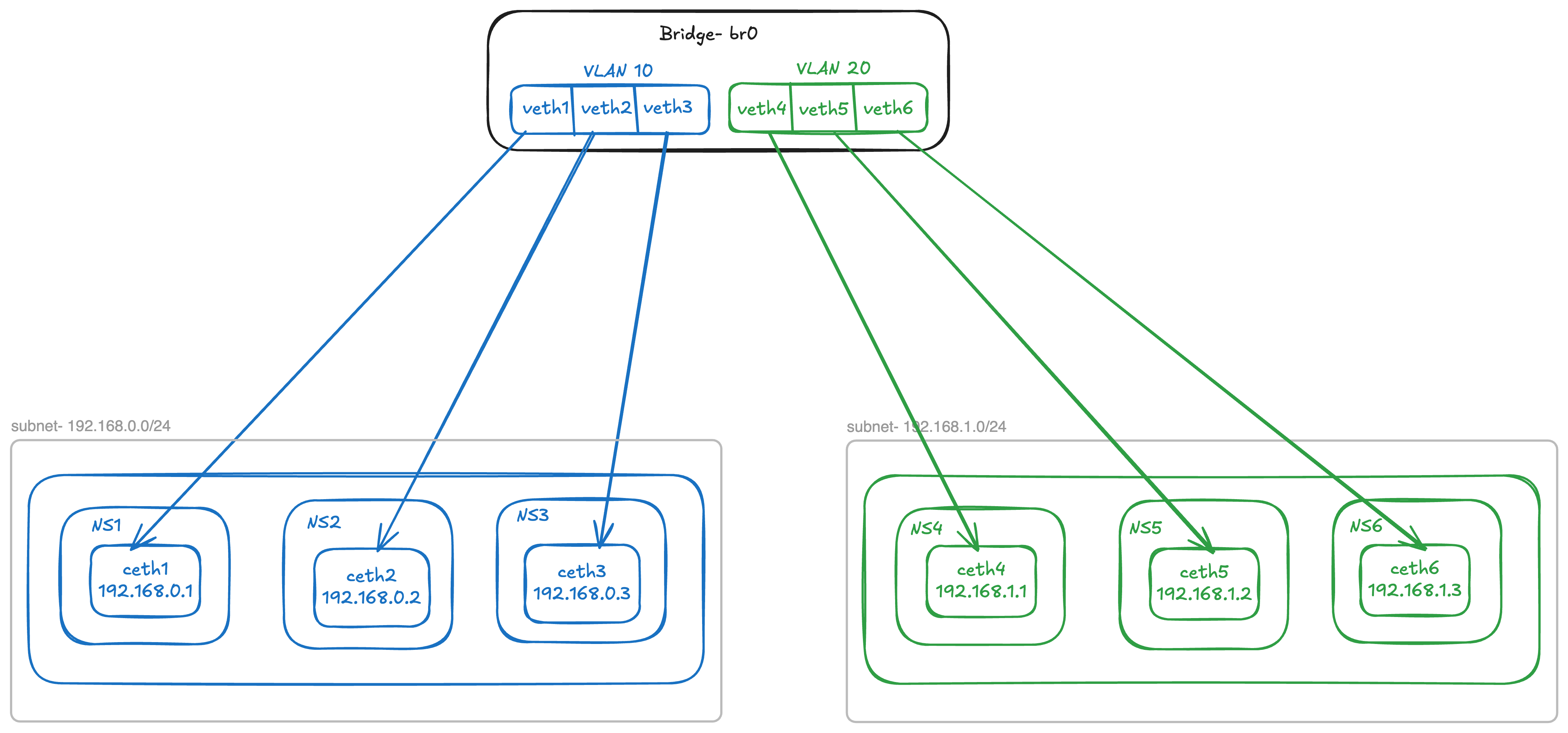
VLAN
Lets modify the setup to add 3 more network namespaces representing 3 more nodes connected to the same bridge but on a different subnet - 192.168.1.0/24
Now if we have following new node configurations:
| Interface | Namespace | IP |
|---|---|---|
ceth4 | ns4 | 192.168.1.1/24 |
ceth5 | ns5 | 192.168.1.2/24 |
ceth6 | ns6 | 192.168.1.3/24 |
When br0 is configured as the master on their host ends, all six nodes share a single broadcast domain. Since a bridge operates as a Layer 2 device, an ARP flood message will reach every node within this broadcast domain. Consequently, an ARP request sent during a ping from 192.168.1.2 to 192.168.1.3 will be heard by all nodes in the 192.168.0.0/24 subnet. This creates an undesirable overlap between the network traffic of two subnets.
ping 192.168.1.2 -> 192.168.1.3 (192.168.1.0/24 subnet traffic)
 1root@ubuntu-01:laborant# ip addr list
 21: lo: <LOOPBACK> mtu 65536 qdisc noop state DOWN group default qlen 1000
 3    link/loopback 00:00:00:00:00:00 brd 00:00:00:00:00:00
 412: ceth4@if13: <BROADCAST,MULTICAST,UP,LOWER_UP> mtu 1500 qdisc noqueue state UP group default qlen 1000
 5    link/ether 1a:cc:a5:0b:b3:52 brd ff:ff:ff:ff:ff:ff link-netnsid 0
 6    inet 192.168.1.2/24 scope global ceth4
 7       valid_lft forever preferred_lft forever
 8    inet6 fe80::18cc:a5ff:fe0b:b352/64 scope link
 9       valid_lft forever preferred_lft forever
10root@ubuntu-01:laborant# ping -c 1 192.168.1.3
11PING 192.168.1.3 (192.168.1.3) 56(84) bytes of data.
1264 bytes from 192.168.1.3: icmp_seq=1 ttl=64 time=0.098 ms
13
14--- 192.168.1.3 ping statistics ---
151 packets transmitted, 1 received, 0% packet loss, time 0ms
16rtt min/avg/max/mdev = 0.098/0.098/0.098/0.000 ms
tcpdump on 192.168.1.3 node
 1root@ubuntu-01:laborant# ip addr list
 21: lo: <LOOPBACK> mtu 65536 qdisc noop state DOWN group default qlen 1000
 3    link/loopback 00:00:00:00:00:00 brd 00:00:00:00:00:00
 416: ceth6@if17: <BROADCAST,MULTICAST,UP,LOWER_UP> mtu 1500 qdisc noqueue state UP group default qlen 1000
 5    link/ether 4a:e8:06:19:53:68 brd ff:ff:ff:ff:ff:ff link-netnsid 0
 6    inet 192.168.1.3/24 scope global ceth6
 7       valid_lft forever preferred_lft forever
 8    inet6 fe80::48e8:6ff:fe19:5368/64 scope link
 9       valid_lft forever preferred_lft forever
10root@ubuntu-01:laborant# tcpdump -i ceth6 -e -n
11tcpdump: verbose output suppressed, use -v[v]... for full protocol decode
12listening on ceth6, link-type EN10MB (Ethernet), snapshot length 262144 bytes
1318:06:38.439217 1a:cc:a5:0b:b3:52 > ff:ff:ff:ff:ff:ff, ethertype ARP (0x0806), length 42: Request who-has 192.168.1.3 tell 192.168.1.2, length 28
1418:06:38.439239 4a:e8:06:19:53:68 > 1a:cc:a5:0b:b3:52, ethertype ARP (0x0806), length 42: Reply 192.168.1.3 is-at 4a:e8:06:19:53:68, length 28
1518:06:38.439257 1a:cc:a5:0b:b3:52 > 4a:e8:06:19:53:68, ethertype IPv4 (0x0800), length 98: 192.168.1.2 > 192.168.1.3: ICMP echo request, id 2348, seq 1, length 64
1618:06:38.439269 4a:e8:06:19:53:68 > 1a:cc:a5:0b:b3:52, ethertype IPv4 (0x0800), length 98: 192.168.1.3 > 192.168.1.2: ICMP echo reply, id 2348, seq 1, length 64
1718:06:43.593966 4a:e8:06:19:53:68 > 1a:cc:a5:0b:b3:52, ethertype ARP (0x0806), length 42: Request who-has 192.168.1.2 tell 192.168.1.3, length 28
1818:06:43.593994 1a:cc:a5:0b:b3:52 > 4a:e8:06:19:53:68, ethertype ARP (0x0806), length 42: Reply 192.168.1.2 is-at 1a:cc:a5:0b:b3:52, length 28
ARP floods are also visible in tcpdump of ceth3 interface with IP 192.168.0.3 of 192.168.0.0/24 subnet
 1oot@ubuntu-01:laborant# ip link list
 21: lo: <LOOPBACK> mtu 65536 qdisc noop state DOWN mode DEFAULT group default qlen 1000
 3    link/loopback 00:00:00:00:00:00 brd 00:00:00:00:00:00
 49: ceth3@if10: <BROADCAST,MULTICAST,UP,LOWER_UP> mtu 1500 qdisc noqueue state UP mode DEFAULT group default qlen 1000
 5    link/ether 52:f2:9f:46:e4:69 brd ff:ff:ff:ff:ff:ff link-netnsid 0
 6root@ubuntu-01:laborant# ip addr list
 71: lo: <LOOPBACK> mtu 65536 qdisc noop state DOWN group default qlen 1000
 8    link/loopback 00:00:00:00:00:00 brd 00:00:00:00:00:00
 99: ceth3@if10: <BROADCAST,MULTICAST,UP,LOWER_UP> mtu 1500 qdisc noqueue state UP group default qlen 1000
10    link/ether 52:f2:9f:46:e4:69 brd ff:ff:ff:ff:ff:ff link-netnsid 0
11    inet 192.168.0.3/24 scope global ceth3
12       valid_lft forever preferred_lft forever
13    inet6 fe80::50f2:9fff:fe46:e469/64 scope link
14       valid_lft forever preferred_lft forever
15root@ubuntu-01:laborant# tcpdump -i ceth3 -e -n
16tcpdump: verbose output suppressed, use -v[v]... for full protocol decode
17listening on ceth3, link-type EN10MB (Ethernet), snapshot length 262144 bytes
1818:06:38.439221 1a:cc:a5:0b:b3:52 > ff:ff:ff:ff:ff:ff, ethertype ARP (0x0806), length 42: Request who-has 192.168.1.3 tell 192.168.1.2, length 28
And the reason is simple: the destination MAC address for ARP request “who-has 192.168.1.3 tell 192.168.1.2” is ff:ff:ff:ff:ff:ff, which means the bridge will broadcast the message to all connected ports. Hence, all interfaces of the other subnet will also receive the ARP request. This is undesirable, as subnets are mainly created to group traffic between different types of entities in a single network.
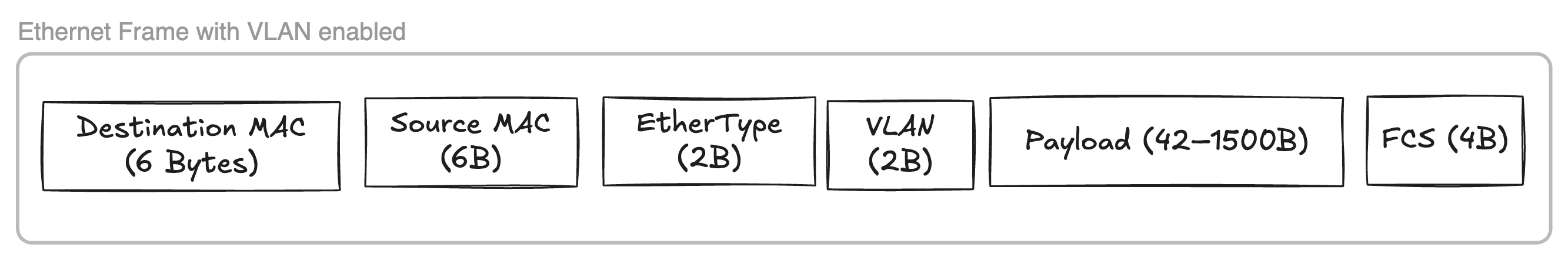
VLAN tagging can be used to tag nodes of one subnet with a id which helps in partitioning the broadcast domain.
 We can configure VLAN at the end hosts or at the bridge itself, where bridge will store the mapping for a port and corresponding
 vlan-id.
If we look at the currently configured vlan-id at the bridge:
1laborant@ubuntu-01:~$ bridge vlan
2port              vlan-id
3veth1             1 PVID Egress Untagged
4veth2             1 PVID Egress Untagged
5veth3             1 PVID Egress Untagged
6veth4             1 PVID Egress Untagged
7veth5             1 PVID Egress Untagged
8veth6             1 PVID Egress Untagged
9br0               1 PVID Egress Untagged
Each of the port is configured with vlan-id 1 and is configured Untagged for egress traffic, That means bridge will not tag the outgoing traffic with the VLAN ID = 1 in ethernet frame (as shown above) which is fine since currently all the ports have same vlan-id.
Lets configure the bridge to have vlan-id = 10 for 192.168.0.0/24 subnet and vlan-id = 20 for 192.168.1.0/24 subnet.
 1# Removing exisiting vid 1 from all ports
 2laborant@ubuntu-01:~$ sudo bridge vlan del dev veth1 vid 1
 3laborant@ubuntu-01:~$ sudo bridge vlan del dev veth2 vid 1
 4laborant@ubuntu-01:~$ sudo bridge vlan del dev veth3 vid 1
 5laborant@ubuntu-01:~$ sudo bridge vlan del dev veth4 vid 1
 6laborant@ubuntu-01:~$ sudo bridge vlan del dev veth5 vid 1
 7laborant@ubuntu-01:~$ sudo bridge vlan del dev veth6 vid 1
 8
 9# Adding new VIDs per subnet
10laborant@ubuntu-01:~$ sudo bridge vlan add dev veth1 vid 10 pvid 10
11laborant@ubuntu-01:~$ sudo bridge vlan add dev veth2 vid 10 pvid 10
12laborant@ubuntu-01:~$ sudo bridge vlan add dev veth3 vid 10 pvid 10
13laborant@ubuntu-01:~$ sudo bridge vlan add dev veth4 vid 20 pvid 20
14laborant@ubuntu-01:~$ sudo bridge vlan add dev veth5 vid 20 pvid 20
15laborant@ubuntu-01:~$ sudo bridge vlan add dev veth6 vid 20 pvid 20
16
17# Enable VLAN filtering on bridge br0
18laborant@ubuntu-01:networking$ sudo ip link set br0 type bridge vlan_filtering 1
19
20# New bridge config
21laborant@ubuntu-01:~$ bridge vlan
22port              vlan-id
23veth1             10 PVID
24veth2             10 PVID
25veth3             10 PVID
26veth4             20 PVID
27veth5             20 PVID
28veth6             20 PVID
29br0               1 PVID Egress Untagged
Now lets try to send a broadcast message from ceth4
1laborant@ubuntu-01:networking$ sudo ip netns exec ns4 /home/laborant/networking/l2_send ceth4 ff:ff:ff:ff:ff:ff
2Sent Ethernet frame via ceth4 → ff:ff:ff:ff:ff:ff
All interfaces of vlan=20 heard the broadcast whereas no traffic reached interfaces ceth1, ceth2 and ceth3 of vlan=10.
1root@ubuntu-01:laborant# tcpdump -i ceth5 -e -n
216:15:09.042913 1a:cc:a5:0b:b3:52 > ff:ff:ff:ff:ff:ff, ethertype Unknown (0x88b5), length 29:
3        0x0000:  4c32 2d74 6573 742d 6672 6f6d 2d67 6f    L2-test-from-go
4
5
6root@ubuntu-01:laborant# tcpdump -i ceth6 -e -n
716:15:09.042913 1a:cc:a5:0b:b3:52 > ff:ff:ff:ff:ff:ff, ethertype Unknown (0x88b5), length 29:
8        0x0000:  4c32 2d74 6573 742d 6672 6f6d 2d67 6f    L2-test-from-go
Likewise, when 192.168.1.1 pings 192.168.1.3, the ARP request to resolve 192.168.1.3’s MAC address is exclusively broadcast to interfaces within the 192.168.1.1 subnet that belong to VLAN 20. This illustrates how VLANs contribute to separating traffic between subnets.
1root@ubuntu-01:laborant# tcpdump -i ceth5 -e -n
216:25:25.134826 1a:cc:a5:0b:b3:52 > ff:ff:ff:ff:ff:ff, ethertype ARP (0x0806), length 42: Request who-has 192.168.1.3 tell 192.168.1.1, length 28
3
4
5root@ubuntu-01:laborant# tcpdump -i ceth6 -e -n
616:25:25.134838 1a:cc:a5:0b:b3:52 > ff:ff:ff:ff:ff:ff, ethertype 802.1Q (0x8100), length 46: vlan 20, p 0, ethertype ARP (0x0806), Request who-has 192.168.1.3 tell 192.168.1.1, length 28
Following diagram shows how VLAN separates traffic of two subnets by enabling VLAN filtering at the bridge level.
Conclusion
In this post, we explored how L1, L2, and L3 network segments are formed and how the different layers of the OSI model work together in practice using Linux network namespaces. We began with pure Layer 2 communication using MAC addresses, examined broadcast domains and MAC learning behavior in a bridge, and then built on top of that to understand Layer 3 communication using IP and ARP. Through packet captures, we clearly saw how ARP bridges the gap between IP addressing and Ethernet, and how broadcast domains define the scope of Layer 2 visibility. Finally, by introducing VLANs, we demonstrated how broadcast domains can be cleanly partitioned within a single Layer 2 infrastructure, reinforcing the separation between Layer 2 forwarding and Layer 3 addressing while still allowing scalable and structured network designs.
References
https://labs.iximiuz.com/courses/computer-networking-fundamentals - A great place to experiment with contents of this blog. This blog post is inspired from the course itself - Highly recommended.